- Company
- Semiconductor Equipment RelatedThermo-electric Modules
- Automotive Related
- Semiconductor Equipment RelatedFerrofluidic Seals (FerroSeals)
- Semiconductor Equipment RelatedCVD-SiC
- Semiconductor Equipment RelatedFine Ceramics Components
- Semiconductor Equipment RelatedMachinable Ceramics Components
- Electronic Device RelatedFerrofluid
- Semiconductor Equipment/Electronic DevicesChillers
Thermo-electric Modules
Technology
Technical information
A thermoelectric module (TEM), also called a thermoelectric cooler (TEC) or Peltier devices, is a semiconductor based electronic component that functions as a compact and efficient heat pump. By applying a low voltage DC power source to a TEM, heat will be moved through the module from one side to the other. One module face, therefore, will be cooled while the opposite face simultaneously is heated.
It is important to note that this phenomenon is fully reversible whereby a change in the polarity of the applied DC voltage will cause heat to be moved in the opposite direction. Consequently, a TEM may be used for both cooling and heating in a given application. A TEM generally consists of two or more semiconductor elements (n-type and p-type), usually made of bismuth telluride (Bi 2Te3), that are connected electrically in series and thermally in parallel. These thermoelectric elements and their interconnects typically are mounted between two thin metalized ceramic substrates, which provide structural integrity, insulate the elements electrically from external mounting surfaces, and provide flat and parallel contact surfaces.
Both n-type and p-type Bi2Te3 materials are used in a TEM. This arrangement causes heat to move through the cooler in one direction only while the electrical current moves back and forth alternately between the top and bottom substrates through each n-type and p-type element.
The n-type material is doped to have an excess of electrons while the p-type material is doped to have a deficiency of electrons. The extra electrons in the n-material and the holes resulting from the deficiency of electrons in the p-material serve as carriers. These carriers move the heat energy through the Bi2Te3 materials. Heat flux (the heat actively pumped through the TEM) is proportional to the magnitude of the applied DC electric current. By regulating the input current from zero to maximum, one can adjust and precisely control the heat flow and module temperature differential. Our thermo-electric modules typically have 7 to 128 couples. TEMs with over 391 couples are also available. The maximum operating current is 1.2 to 36A in the catalog. Other products are also available.
TEMs can be mounted in parallel to increase the heat transfer capacity, or they can be stacked in multistage cascades to increase the temperature differential.
TEMs have no moving parts, so they are reliable and virtually maintenance free. They are also smaller, lighter and quieter than comparable mechanical cooling systems. However, TEMs are not ideal for every cooling application, and there are situations in which a simple passive cooling device, such as a heat sink, is more appropriate. There are also situations in which thermoelectric cooling is the only suitable solution, or for which it presents significant advantages over other cooling methods.
TEMs can provide active cooling, which means they cool below ambient temperature, which is not possible with heat sinks alone. Their solid-state construction ensures high reliability, which is an advantage when they are to be used in a system that is not easily accessible after installation. Operation is acoustically silent and electrical interference is negligible.
Selection of the proper TEM for a specific application requires an evaluation of the total system in which the TEM will be used. For most applications it should be possible to use a standard TEM configuration, while in certain cases a special design may be needed to meet stringent heat pumping, electrical, mechanical, or other design requirements. Although we encourage the use of a standard TEM whenever possible, Ferrotec specializes in the development and manufacture of custom TEMs. We will be pleased to provide technical analysis to define a unique TEM design that meets your requirements precisely.
Most cooling systems are dynamic in nature, and overall system performance is a function of several interrelated parameters. * If there is any uncertainty about which TEM would be most suitable for a particular application, we recommend that you contact our sales team or your local representative for assistance.
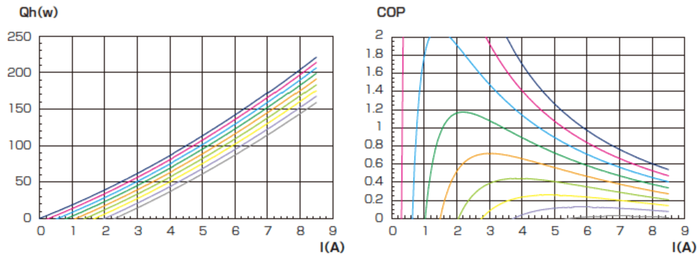
- *Each application will have its own set of parameters that will impact the temperature of the TEM hot side (Th). Performance data is presented graphically and there are four important attribute graphs explaining the TEM performance.
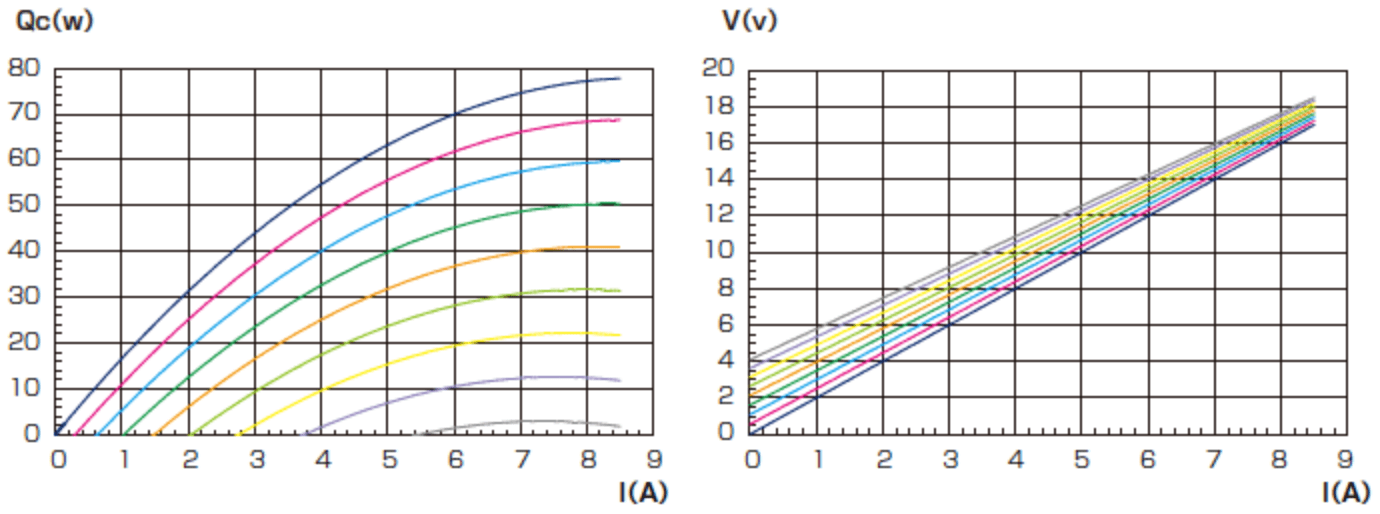
ΔT = 0°C ΔT = 10°C ΔT = 20°C ΔT = 30°C ΔT = 40°C ΔT = 50°C ΔT = 60°C ΔT = 70°C ΔT = 80°C
Qc vs. I
This graph shows the TEM's heat pumping capacity (Qc) in watts at a fixed level of Th as a function of input current (I) at various differential temperatures across the TEM (ΔT). This data allows the user to determine whether the module under consideration has sufficient heat removal capacity to meet the application requirements.
V vs. I
A graph of V vs. I depicts the voltage necessary to produce the current needed at various differential temperatures. If you have selected an appropriate TEM, established the correct operating current from the Qc vs. I graph, and figured out the ΔT value, you can use this chart to determine the power supply requirements.
Qh vs. I
The graph Qh vs. I shows the expelled heat (Qh) in watts, from the hot side of the TEM as a function of the current level (I) at a specific Th level. The quantity Qh is the sum of Qc (cooling capacity) and I x V (electrical power I).
COP vs. I
This important graph relates the coefficient of performance (COP) and ΔT to input current. The COP is equal to the pumped heat divided by the input power. This graph enables the user to determine the coefficient of performance (efficiency) to maximize the cooling capacity and minimize the heat rejected to the heat sink.